A dam site, from baseline to observation.
A hydropower workflow connects three different kinds of information: surveyed site geometry, instrument observations and the software used to review them. LiDAR establishes a spatial baseline. Water, weather and local deformation instruments add time-dependent observations. A software workspace keeps the measurement method, reference and history beside the place being reviewed.
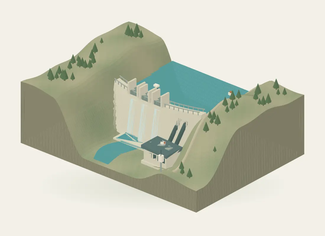
Explore the same site in the interactive experience.
Capture the site baseline
Survey the accessible dam structures, terrain, access routes and existing facilities. Define control, coverage and required sections or models around the engineering task. Laser scanning of the surrounding geometry does not provide a reservoir bathymetric survey or measure through the water.
Keep hydraulic and local measurements distinct
Reservoir elevation, local tailrace stage, rainfall and water quality describe different parts of the site. A discharge estimate needs an appropriate local hydraulic method, such as a surveyed cross-section and calibrated velocity relationship. Joint gauges and borehole extensometers describe their own installed locations and axes; they do not measure the movement of the entire dam.
Review the histories in context
Connect the model to time-series data, local references and inspection notes. Separate sensor acquisition, data receipt and survey epochs. A chart can reveal a pattern worth investigating, but correlation between rainfall, turbidity and movement is not a causal explanation or a dam-safety assessment.
Inputs to agree
- Survey extent, access constraints and required sections or models
- Coordinate control and local water-level references
- Instrument locations, hydraulic method and calibration information
- Data interfaces, review responsibilities and reporting intervals
Possible outputs
- Registered point clouds, drawings or terrain/model deliverables
- Water, weather and local deformation histories with measurement context
- Spatial review of observations and inspection notes
- Reports that preserve references, timestamps and quality notes
Keep the measurements distinct
| Quantity | Unit or component | Interpretation |
|---|---|---|
| Water elevation | m against a stated datum | Water-surface height; not reservoir storage. |
| Discharge | m³/s | Flow rate from an appropriate calibrated hydraulic method. |
| Storage | m³ | Volume from suitable geometry or an elevation–volume relationship. |
| Turbidity | Method-specific optical units | NTU and FNU are not interchangeable labels. |
Can reservoir level be used directly to calculate discharge?
No. Reservoir elevation is not the local velocity or flow area at an outlet. Discharge needs a justified hydraulic relationship and suitable inputs. Reservoir storage also needs an elevation–volume relationship or appropriate survey geometry; a level reading alone is not a stored volume.
Does turbidity measure sediment concentration?
Not directly. Turbidity is an optical observation whose units depend on the measurement method. A site-specific relationship and sampling programme are needed before inferring sediment concentration. Fouling, bubbles and calibration conditions also affect interpretation.
Technical references
- USGS: turbidity measurement methods and units
- OTT: local level, surface velocity and discharge application
Further reading on the measurement principles discussed above.
Content reviewed · Skyrover